Computational Graphic final project
- Student Roberto Manca
- Student ID 415870
- GitHub @octawizard
The subject
The architect: Le Corbusier
 Charles-Édouard Jeanneret-Gris, better known as Le Corbusier (October 6, 1887 – August 27, 1965), was an architect, designer, painter, urban planner, writer, and one of the pioneers of what is now called modern architecture. He was born in Switzerland and became a French citizen in 1930. His career spanned five decades, with his buildings constructed throughout Europe, India, and America. He was a pioneer in studies of modern high design and was dedicated to providing better living conditions for the residents of crowded cities. He was awarded the Frank P. Brown Medal and AIA Gold Medal in 1961.
Le Corbusier adopted his pseudonym in the 1920s, allegedly deriving it in part from the name of an ancestor, Lecorbésier.
Charles-Édouard Jeanneret-Gris, better known as Le Corbusier (October 6, 1887 – August 27, 1965), was an architect, designer, painter, urban planner, writer, and one of the pioneers of what is now called modern architecture. He was born in Switzerland and became a French citizen in 1930. His career spanned five decades, with his buildings constructed throughout Europe, India, and America. He was a pioneer in studies of modern high design and was dedicated to providing better living conditions for the residents of crowded cities. He was awarded the Frank P. Brown Medal and AIA Gold Medal in 1961.
Le Corbusier adopted his pseudonym in the 1920s, allegedly deriving it in part from the name of an ancestor, Lecorbésier.
His work in the early days hampered by its alleged "revolutionary" nature and the radical look it acquired from experiences "purist" with the passing of time has had and continues to have the proper recognition.
His message is being increasingly absorbed by large sections of user, and his attitude of avant-gardism to the bitter end must be interpreted in the right measure, recognizing that in its design method, the use of rational systems with extremely simple forms and shapes, based on the functional logic.
Le Corbusier's furniture
Le Corbusier said: "Chairs are architecture, sofas are bourgeois".
Le Corbusier began experimenting with furniture design in 1928 after inviting the architect, Charlotte Perriand, to join his studio. His cousin, Pierre Jeanneret, also collaborated on many of the designs. Before the arrival of Perriand, Le Corbusier relied on ready-made furniture to furnish his projects, such as the simple pieces manufactured by Thonet, the company that manufactured his designs in the 1930s.
In 1928, Le Corbusier and Perriand began to put the expectations for furniture Le Corbusier outlined in his 1925 book L'Art Décoratif d'aujourd'hui into practice. In the book he defined three different furniture types: type-needs, type-furniture, and human-limb objects. He defined human-limb objects as: "Extensions of our limbs and adapted to human functions that are type-needs and type-functions, therefore type-objects and type-furniture. The human-limb object is a docile servant. A good servant is discreet and self-effacing in order to leave his master free. Certainly, works of art are tools, beautiful tools. And long live the good taste manifested by choice, subtlety, proportion, and harmony".
The first results of the collaboration were three chrome-plated tubular steel chairs designed for two of his projects, La Maison La Roche in Paris and a pavilion for Barbara and Henry Church. The line of furniture was expanded for Le Corbusier's 1929 Salon d'Automne installation, 'Equipment for the Home'.
In the year 1964, while Le Corbusier was still alive, Cassina S.p.A. of Milan acquired the exclusive worldwide rights to manufacture his furniture designs. Today many copies exist, but Cassina is still the only manufacturer authorized by the Fondation Le Corbusier.

Chosen furniture
The goal was to use a modular approach to create several models of furniture, carefully choosing how to decompose each model into submodels, then properly assemble all the components.
Very important furniture were the LC-2, LC-3, and LC-4 models, originally titled "Fauteuil grand confort, petit modèle" (LC-2, "great comfort sofa, small model"), "Fauteuil grand confort, grand modèle" (LC-3, "great comfort sofa, large model"), and "Chaise longue" (LC-4, "Long chair").The LC-2 and LC-3 are more colloquially referred to as the "petit confort" and "grand confort" (abbreviation of full title, and due to respective sizes). The LC-2 (and similar LC-3) have been featured in a variety of media, notably the Maxell "blown away" advertisement.
LC2, LC3 and LC4 were chosen for their elegance, beauty of design and ability to take advantage of the modular approach required for this project. As evidence of the use of that approach, it should also be noted that LC2 and LC3 are generated by the same code, changing only the parameter that represents the couch number of seats.
Were also modeled LC10, which is a simple but elegant low table suitable for a living room, and LC16 together with LC14, which make up an elegant wood colored library accompanied by a small table and two singular chairs with same color; once again a modular approach to modeling is very useful in terms of elegance of code and facilitation of assembly of the various components.
All components have been chosen in order to furnish an elegant living room with the beautiful indoor models designed by the genius of Le Corbusier.
At first the models have been implemented as prototypes using the Python module Pyplasm, only to be finished and detailed in a second stage, exploiting plasm.js. Having all models a high level of detail, each one has been implemented in a different file, in order to make the run of the script as quick as possible.
The Project
LC2 Petit Modèle with LC3 Fauteuil grand confort, grand modèle (1928)
"Armchair, two-or three-seater and ottoman with polished chrome steel, which can be painted in various colors. Loose cushions with polyurethane foam and polyester wadding or feather with polyurethane foam insert. Cover in leather or fabric."
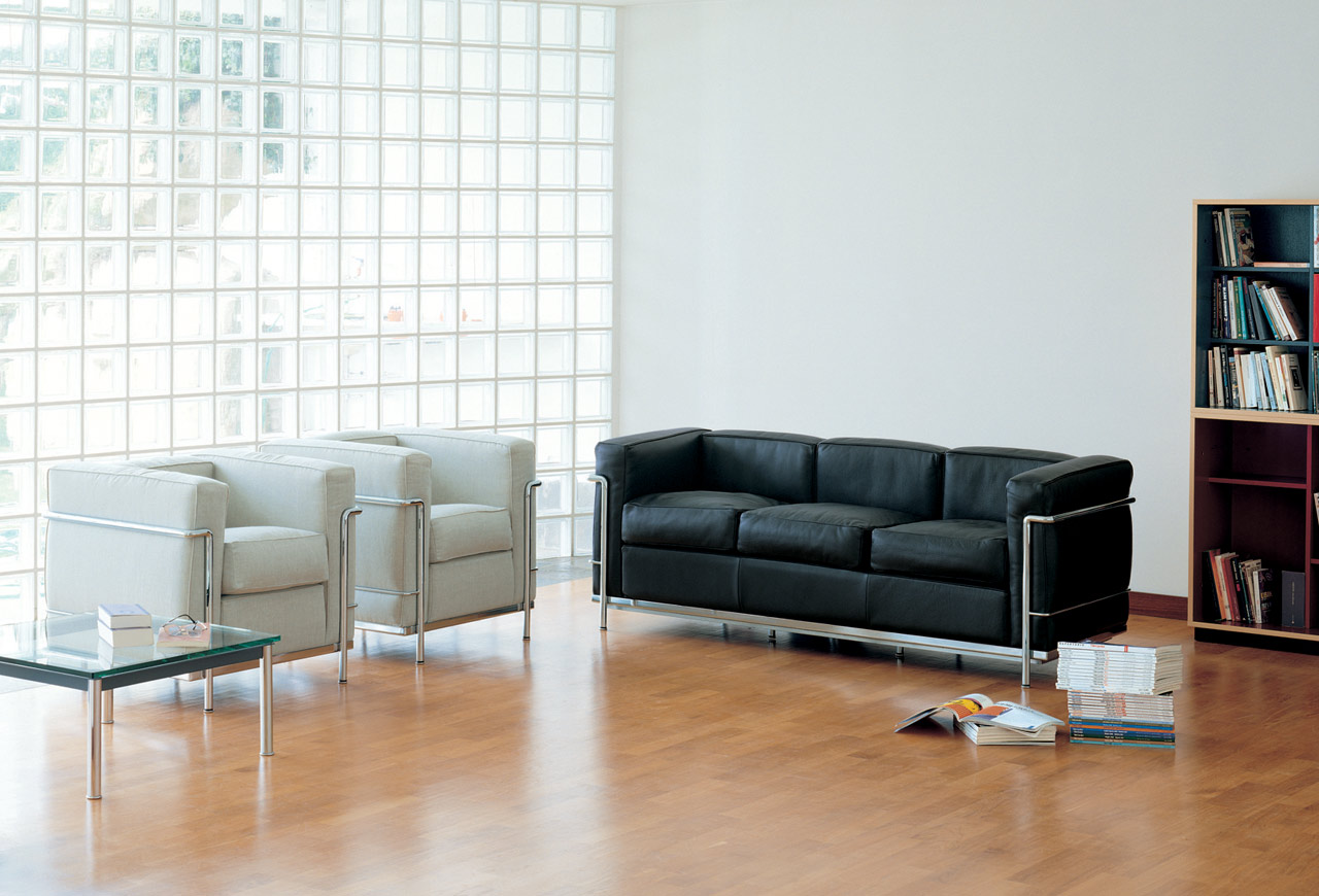
The basic idea was to decompose the model of LC2 into two coarse grain parts, the seat and the arms of the sofa. To implement from time to time a single armchair or a sofa with a variable number of seats, the idea was to replicate a number of times equal to the number of seats the sub-model seat and placing armrests to the extremes of this new submodel obtained.
Increasing the level of detail of decomposition, we have that the two parts are in turn divided into smaller sub-models. For example, the seat is divided into subparts that represent the various cushions that compose it, as well as the frame tubes encircling it on the back. Regarding the armrests, we have a decomposition in a complex system of pipes that forms the structure on which rest the sofa pillows. There are several decomposotion levels, until arriving to the building of elementary objects to assemble.
This 2D model was used as a reference (property of Cassina S.p.A.)

Below are shown the various components of the prototype developed using the Python module Pyplasm. Subsequently is shown the prototype resulting from the assembly of its various components.

Every part of the pipe is built using the PLASM function CUBIC_HERMITE, which allows to obtain a regular pipe, with constant diameter even when there are changes of direction along the various plane axes. The example below shows the javascript code used to implement a generic part of the pipe.
$   c1 = CUBIC_HERMITE(S0)([[dx + 0.38, 0, 5.33],[dx + 0.38 +0.22+0.1, 0, 5.33+0.34],[0,0,0.75],[0.75,0,0]])
$   c2 = CUBIC_HERMITE(S0)([[dx + 0.38 +0.22, 0, 5.33],[dx + 0.38 +0.22+0.1, 0, 5.33 +0.12],[0,0,0.25],[0.25,0,0]])
$   sur1 = CUBIC_HERMITE(S1)([c1,c2,[0,0.44,0],[0,-0.44,0]])
$   sur1 = MAP(sur1)(domain2D)
$   sur2 = CUBIC_HERMITE(S1)([c1,c2,[0,-0.44,0],[0,0.44,0]])
$   sur2 = MAP(sur2)(domain2D)
$   f1x = STRUCT([sur1, sur2])
Another interesting part is that relating to the algorithm used to distribute the seats of the sofa, from the origin of the axes. Shown below is the javascript code that implements it. The function getSeats takes as parameters the seat length on the x-axis, and the total number of seats of the couch (with n greater or equal to one).
$   function getSeats(dx, n){
$   var seat = STRUCT([getSeatSkeleton(dx+0.05), getSeatPillows(dx)]);
$   var seats = [];
$   var j = 1;
$   var i;
$   if (n % 2 === 0){
$      for (i=1; i<=n; i=i+2){
$         if (i===1){
$             seats.push(T([0])([dx])(seat), T([0])([-dx])(seat));
$         }
$         else {
$           seats.push(T([0])([j*2*dx + dx])(seat));
$           seats.push(T([0])([(j*2*dx + dx)*-1])(seat));
$           j++;
$         }
$       }
$   }
$   else{
$     seats.push(seat);
$     for (i=2; i<=n; i=i+2){
$         seats.push(T([0])([2*dx*j])(seat), T([0])([-2*dx*j])(seat));
$         j++;
$     }
$   }
$   var all_seats = STRUCT(seats);
$   return (all_seats);
$}
In the following code is instead shown the composition of the sub-models, coarse, which are placed in a STRUCT to assemble the model LC2 in case of an armchair, or LC3 in the case of a sofa. Note that the models arms and seats are in turn broken down into simpler submodels.
$   var seats = getSeats(seat_dx/2, numberOfSeats);
$   var arms = getArms(seat_dx/2, numberOfSeats);
$   var modelLC2 = STRUCT([seats, arms, getAdditionalPipes(seat_dx/2, numberOfSeats)]);
$   DRAW(modelLC2);
Here is a picture of the LC2 complete model implemented by exploiting plasm.js.


Click to see full screen running plasm.js LC3 model.
LC4 Chaise Longue à réglage continu (1928)
"Chaise-longue with variable inclination, cradle steel with polished chrome or matte black enamel. Steel pedestal painted matt black. Mattress with headrest padding polyester wadding".
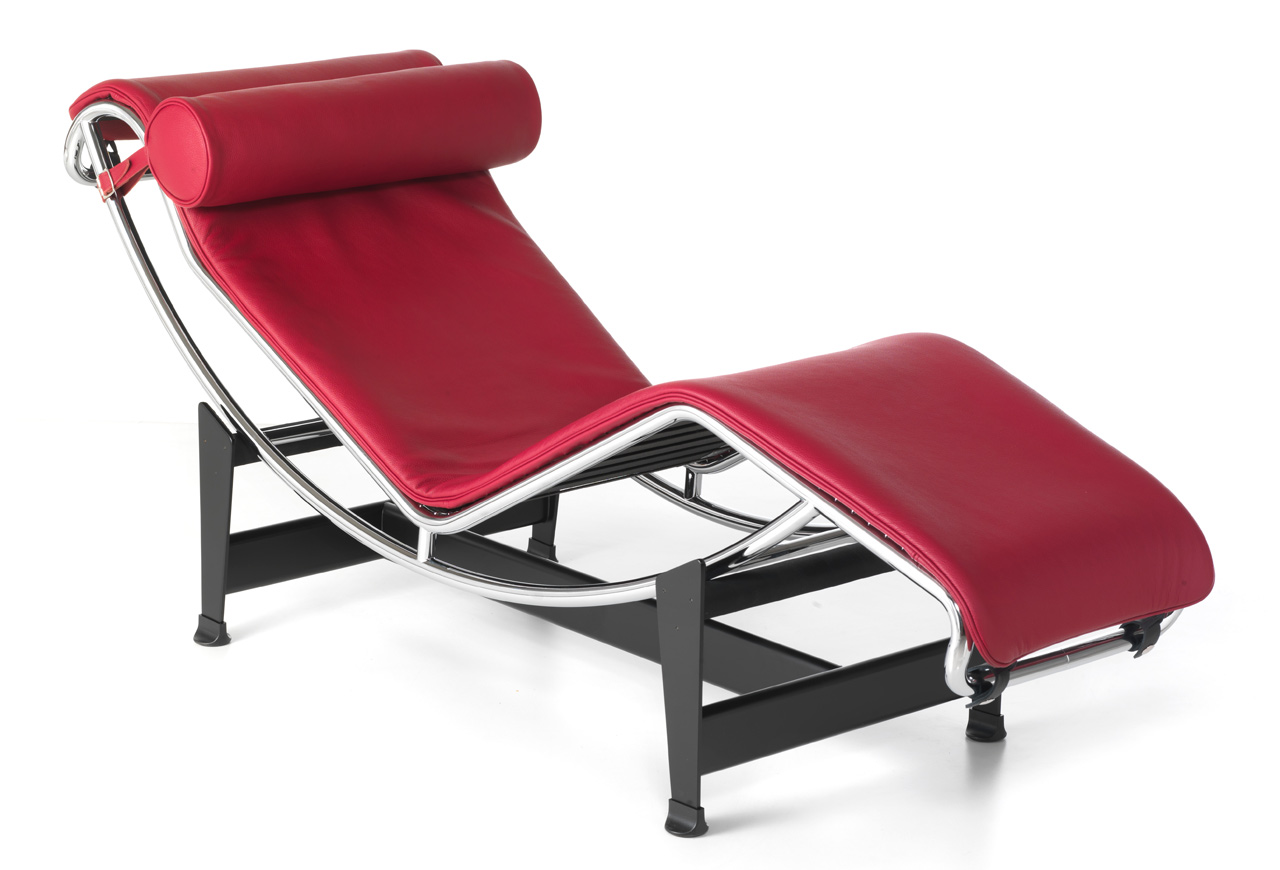
The model of LC4 was perhaps the most complex of those implemented. To facilitate its modeling, it was decided to center it along the x axis. Note how the model is not even constant on the y axis; in fact, looking from above, you can see how the Long Chair go to shrink in width in the vicinity of the end of the little mattress. The model has been decomposed into the following parts: feet, down pipes, upper pipes, table and pillow. Each of the submodels is in turn decomposed into other submodels, also very complex ones, as in the case of tubes that make up the frame of LC4. Regarding the modeling of the tubes of the frame, the approach used has been to draw first "frontal" ones (taking as a reference an image like this) and then those "on the back", properly mirroring the "frontal" along the y-axis. The following step was connecting the two.
This 2D model was used as a reference (property of Cassina S.p.A.)

Below are shown the various components of the prototype developed using the Python module Pyplasm and then the full prototype, resulting from the assembly of its various components.

In the LC4 model, the pipes are implemented with the BEZIER function; the choice was mandatory, as the shape of the tubes followed curves which changed along three axes together. This fact does not allow the use of the function CUBIC_HERMIT, as it was not possible to define the tangent vector of departure and arrival of the surface without avoiding the strong change in diameter of the pattern of the resulting tube. So were defined four Bezier curves, representatives together the profile of the pipe to be modeled. Then they were themselves passed to the function BEZIER three at a time, to create the surface of the half pipe. Much the same for the other half. This operating way is effective in that the tubes are small and are unable to notice the otherwise annoying effect due arrival with different gradients to the destination and departure curve, which are those to be interpolated. Following there's an example of that approach.
$   function getTubeBack(){
$   var b1 = BEZIER(S0)([[-7.75 +0.1, 5.5, 7], [-5, 5.5-0.2, 0.9], [0, 5.5-0.4, 0], [4, 5.5-0.6, 2.5], [4.5, 5.5-0.7, 3], [5.9 -0.1, 5.5-0.8, 3.5]]);
$   var b2 = BEZIER(S0)([[-7.75 +0.1, 5.5-0.1, 7], [-5, 5.5-0.3, 0.9], [0, 5.5-0.5, 0], [4, 5.5-0.7, 2.5], [4.5, 5.5-0.8, 3], [5.9 -0.1, 5.5-0.9, 3.5]]);
$   var b12 = BEZIER(S0)([[-7.75 +0.2, 5.5-0.05, 7], [-5, 5.5-0.1, 1], [0, 5.5-0.45, 0.1], [4, 5.5-0.65, 2.6], [4.5, 5.5-0.75, 3.1], [5.9 -0.2, 5.5-0.85, 3.6]]);
$   var b21 = BEZIER(S0)([[-7.75 -0.1, 5.5-0.05, 7], [-5, 5.5-0.1, 0.8], [0, 5.5-0.45, -0.1], [4, 5.5-0.65, 2.4], [4.5, 5.5-0.75, 2.9], [5.9, 5.5-0.85, 3.4]]);

$   var t1 = BEZIER(S1)([b1,b12,b2]);
$   t1 = MAP(t1)(domain2D);
$   var t2 = BEZIER(S1)([b1,b21,b2])
$   t2 = MAP(t2)(domain2D);
$   return STRUCT([t1, t2])
$   }
It is noted as mentioned earlier: the models shown below are themselves decomposed into several sub-models, especially in the case of the down pipes and upper pipes.
$   var feet = STRUCT([getFeetFront(), getFeetBack()]);
$   var down_pipes = STRUCT([getTrasversalTubes(), getTubeFront(), getTubeBack(), getTrasversalPillars()]);
$   var upper_pipes = STRUCT([getOvalTrasversalPillars(), getUpperBackTubes(), getUpperFrontalTubes(), trasversalUpperTube_1(), trasversalUpperTube_2()]);
$   var table = getTable();
$   var pillow = getPillow();
$   var modelLC4 = STRUCT([feet, down_pipes, upper_pipes, table, pillow])
$   DRAW(modelLC4);
Here is a picture of the LC4 complete model implemented by exploiting plasm.js.

LC10-P Low Table (1928)
"Table downs of square and rectangular, with legs in chromed steel and steel frame. Glass tops or molded glass."
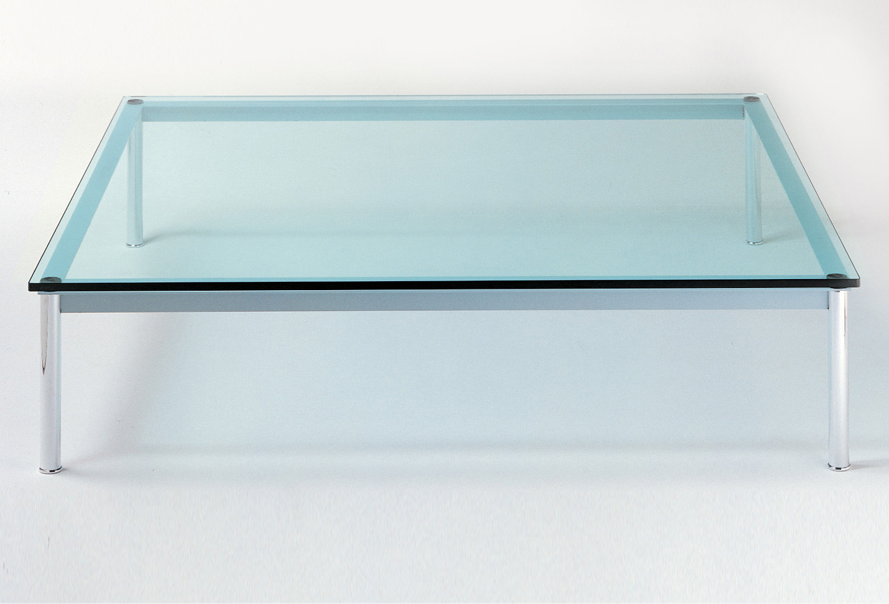
The model of LC10-P is divided into the following components: tableLedge, pillars and junctions. For the implementation of the model was carried out a thorough preliminary phase in which were calculated interesting measurements of the table. These measures were then saved in the code and used as parameters for the correct positioning of the various components in space.
These 2D models were used as a reference (property of Cassina S.p.A.)


Below are shown the various components of the prototype developed using the Python module Pyplasm and then the full prototype, resulting from the assembly of its various components.

For the creation of the table feet, was created a function getPillar that returns a generic model of the pillar, taking as parameters the radius and height of the model. Even here we have a decomposition of the submodel pillar, in its basic components (in the code top, base and p). The pillars that compose the model are then appropriately shifted, based on the parameters related to the size of the table. Here is the code related to the above.
$   function getFullCylinder(r, h, dim){
$     var cyl = CYL_SURFACE([r,h])(dim);
$     var base = DISK(r)(dim);
$     var base2 = T([2])([h])(base);
$     var fullCylinder = STRUCT([cyl, base, base2]);
$     return fullCylinder;
$   }

$   var torus = function (R, r) {
$     return function (v) {
$       var a = v[0];
$       var b = v[1];
$       var u = (r * COS(a)+2*R) * (COS(b));
$       var v = (r * COS(a)+2*R) * (SIN(b));
$       var w = (r * SIN(a));
$       return [u,v,w];
$     }
$   }

$   function getPillar(radius, height) {
$     height = height - final_disk_spessore;
$     var domain = DOMAIN([[0,2*PI],[0,2*PI]])([45,45]);
$     var p = getFullCylinder(radius, height, [32,2]);
$     p = COLOR(light_gray)(p);
$     var mapping = torus(radius/2,radius/4);
$     var base = MAP(mapping)(domain);
$     base = COLOR(light_gray)(base);
$     var top = EXTRUDE([final_disk_spessore])(DISK(radius)([36,2]));
$     top = T([2])([height])(top);
$     top = COLOR([0,0,0])(top);
$     return STRUCT([p, base, top]);
$   }
Here is a picture of the LC10-P complete model implemented by exploiting plasm.js.

LC16 Table De Travail Avec Rayonnages (1957) with LC14-02 Tabouret Maison du Brésil(1952)
"The system of LC16 consists of cabinet and shelf, oak wood, veneer, natural finish. The compartment is equipped with fixed shelves. It is possible to extend the modularity of the cabinet with the item per day, which is can be aggregated to the rest of the system. The LC14 is a stool in solid oak, natural dyed. Present, the two main facades, openings practices that promote the movement of the object."

The unified model of LC16 and LC14 is divided into the following components: library, table and chairs. The component library was constructed using CUBOID models, whose dimensions and positions were obtained in a preliminary model measurement phase. Library has been decomposed into three sub-models, a central library, a right one and left one. These three submodels use the definition of a further submodel of generic library, which is then customized to produce the different kinds of library (central, right and left). The table submodel has been decomposed into two further submodels: the shelf and the pillar on which it stands. The model of chairs, which represents the model of the LC14, was decomposed into submodels that represent the facades of the cuboid-chair. So we have the construction of every type of facade, each of which is replicated and shifted to form the pattern of the parallelepiped.
These 2D models were used as a reference (property of Cassina S.p.A.)


Below are shown the various components of the prototype developed using the Python module Pyplasm and then the full prototype, resulting from the assembly of its various components.

The facade of the chair has an opening in the center. To create the facade correctly, have been used several times the function BEZIER. The first use is to trace the outer and inner contours of the surface. The second is to properly interpolate two by two the contours, to have a slice of facade surface. Assembling all, the surface of the facade is achieved. The code shown below implements this process.
$   def getSurfaceX() :
$     profile_edge_1 = BEZIER(S1)([[-2, -2, 0], [-2, 2, 0]])
$     profile_edge_2 = BEZIER(S1)([[2, -2, 0], [2, 2, 0]])
$     profile_edge_3 = BEZIER(S1)([[-2, -2, 0], [2, -2, 0]])
$     profile_edge_4 = BEZIER(S1)([[-2, 2, 0], [2, 2, 0]])
$
$     inner_profile_edge_1 = BEZIER(S1)([[-0.5, -0.2, 0], [0.5, -0.2, 0]])
$     inner_profile_edge_2 = BEZIER(S1)([[-0.5, 0.2, 0], [0.5, 0.2, 0]])

$     inner_profile_edge_c1 = BEZIER(S1)([[-0.5, -0.2, 0], [-0.7, -0.2, 0], [-0.7, 0.2, 0], [-0.5, 0.2, 0]])
$     inner_profile_edge_c2 = BEZIER(S1)([[0.5, -0.2, 0], [0.7, -0.2, 0], [0.7, 0.2, 0], [0.5, 0.2, 0]])

$     profile_surface_x1 = BEZIER(S2)([profile_edge_3, inner_profile_edge_1])
$     profile_surface_x2 = BEZIER(S2)([profile_edge_4, inner_profile_edge_2])
$     profile_surface_x3 = BEZIER(S2)([inner_profile_edge_c2, profile_edge_2])
$     profile_surface_x4 = BEZIER(S2)([inner_profile_edge_c1, profile_edge_1])

$     sx1 = MAP(profile_surface_x1)(domain2D)
$     sx2 = MAP(profile_surface_x2)(domain2D)
$     sx3 = MAP(profile_surface_x3)(domain2D)
$     sx4 = MAP(profile_surface_x4)(domain2D)

$     surface_x = STRUCT([sx1, sx2, sx3, sx4])
$     return surface_x
$   }
Here is a picture of the LC16 and LC14 complete model implemented by exploiting plasm.js.

Disclaimer
All the original furniture images, their description and the informations about Le Corbusier's life and work, are taken from wikipedia and Cassina's website.